The global electric vehicle On-Board Charger (OBC) market is estimated to reach $10.82 billion by 2027, registering a CAGR of 22.4% from 2020 to 2027. With OBCs that on average give 25% higher DC-DC rating and ~30% reduction in charge duration, Electra EV has been developing OBCs which have helped electric mobility applications exceed end-user expectations.
The specifications of the battery charger influence the charging time and battery life. Let us look into detail about an OBC.

The main function of an on-board charger, is to manage the flow of current from the grid to the traction battery. On-board chargers (OBCs) helps in charging the electric vehicles from any source. Hence, electric vehicles do not have to depend on charging stations all the time.
Another function of OBC is that it controls the level of current and voltage at which the battery is charged. There are mainly two types of charging : constant voltage and constant current charging. Even though constant current charging provides high efficiency and high charging speed it can affect the lifespan of the battery. This is due to over-charging. In the case of constant voltage charging, there is a chance that a high amount of current can flow into the battery initially.
The above problem can be solved by charging the battery initially by constant current charging. Then after reaching a certain amplitude, the battery is charged using constant voltage charging. This charging strategy is the most important role of an on-board charger.
ESVE Charging level AC Supply specification Power rating Time taken to charge a 24kWh battery pack (approx.) AC charging station Level 1 – residential applications Single Phase- 120/230 V and 12 to 16 A 1.44 kW to 1.92 kW 17 hrs AC charging station Level 2- Commercial applications Split Phase – 208/240 V and 15 to 80 A 3.1 kW to 19.2 kW 8 hrs DC charging station Level 3- Fast charging Single Phase- 300/600 V and approx. 400 A 120 kW to 240 kW 30 min

In AC charging level 1 and level 2, the AC power from the grid is converted to DC power by the OBC to charge the battery via the Battery Management System(BMS). The voltage and current regulation is performed by the OBC. In addition, the disadvantage of AC charging is as its charging time increases, the power output becomes low.
The charging rate, or required input current, is determined by the EV itself in AC chargers. Because not all electric vehicles (EVs) require the same amount of input charging current, the AC Charger must communicate with the EV to determine the required input current and establish a handshake before charging can commence. This communication is referred to as Pilot wire communication. The Pilot wire identifies the type of charger attached to the EV and sets the OBC’s required input current.

In DC fast charging or Level 3 charging, the AC power from the grid is directly supplied to the Battery Pack. As shown in the figure above, we can see that there is a AC/DC converter in-built in the DC charger itself. Hence it eliminates the need for OBC in this level of charging. Therefore, this helps in reducing the charging time. The EVSE is arranged in stacks to deliver high current because a single stack will not be able to supply high current. Hence, there is no role of OBC in DC Charging.
There are mainly two types of on-board chargers :
Single phase On-board Charger
Three phase On-board Charger
This classification is based on the number of phases it can use. The output of a standard single phase OBC is 7.2-7.4 kWh. While, that of a three-phase OBC is 22kWh. As a matter of fact, the OBC is able to detect which type of input it can accept. When connected to only one phase, the power that this on-board charger can tolerate is 110 – 260 V AC (and 360 – 440V in the case of using three phases). The battery receives a voltage between 450 and 850 volts as an output.

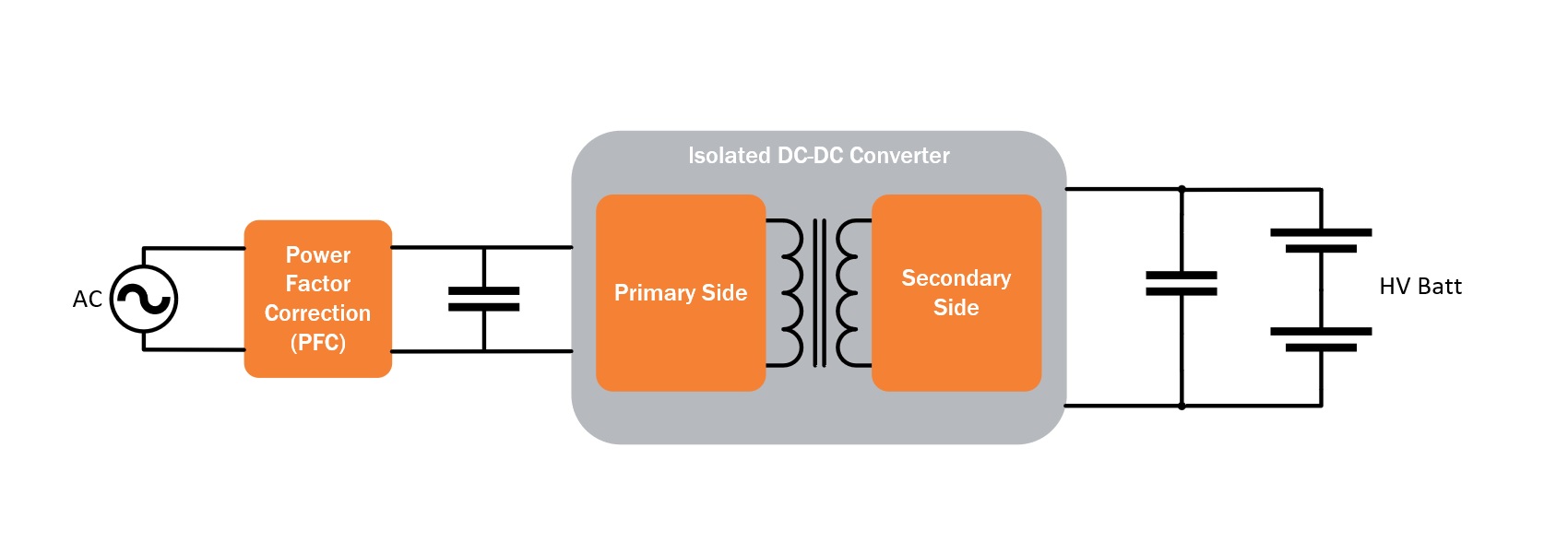
In OBCs using a rectifier, high power AC input is converted to DC power and provides Power Factor Correction. To boost the power factor to unity, a power factor correction (PFC) circuit removes harmonic distortion in the supply current and provides a current waveform that is close to a basic sine wave. This section of the charger determines whether it can use one, two, or all three alternating current phases. In addition, the DC/DC converter must isolate the power grid from the HV dc bus and the HV dc bus from the LV dc bus for safety reasons.
The second phase receives the 700V output voltage. The resultant DC signal is chopped into a square wave, that drives a transformer. This further provides the required DC voltage. An isolated CAN bus can be used to monitor and control the entire system. Digital isolators and digital isolators with integrated DC/DC power converters are used to isolate the CAN. Finally, the required voltage is supplied to the battery.
The factors that needs to be considered before designing the OBCs:
The AC input and the required output level
The maximum power the battery pack can withstand
Temperature cooling and space reduction
Charging time
Rectification of AC signal and Power Factor Correction (PFC)
Communication between the EV and EVSE
Safe isolation between power source and battery
Next:The Best Electric Vehicle Chargers of 2022
Previous:Electric vehicle (EV) on-board chargers (OBC Charger)
Contact Person: Miss. Kiki
| WhatsApp : | +8617763224709 |
|---|---|
| Skype : | +8617763224709 |
| WeChat : | +8617763224709 |
| Email : | kiki@lifepo4-battery.com |