


The smallest unit of electrochemical energy storage is the battery cell, taking lithium iron phosphate cells as an example, which have a voltage of 3.2V. Currently, mainstream energy storage cells have capacities ranging from 120Ah to 280Ah. For large-scale electrochemical energy storage systems, the entire architecture can be divided into three parts.
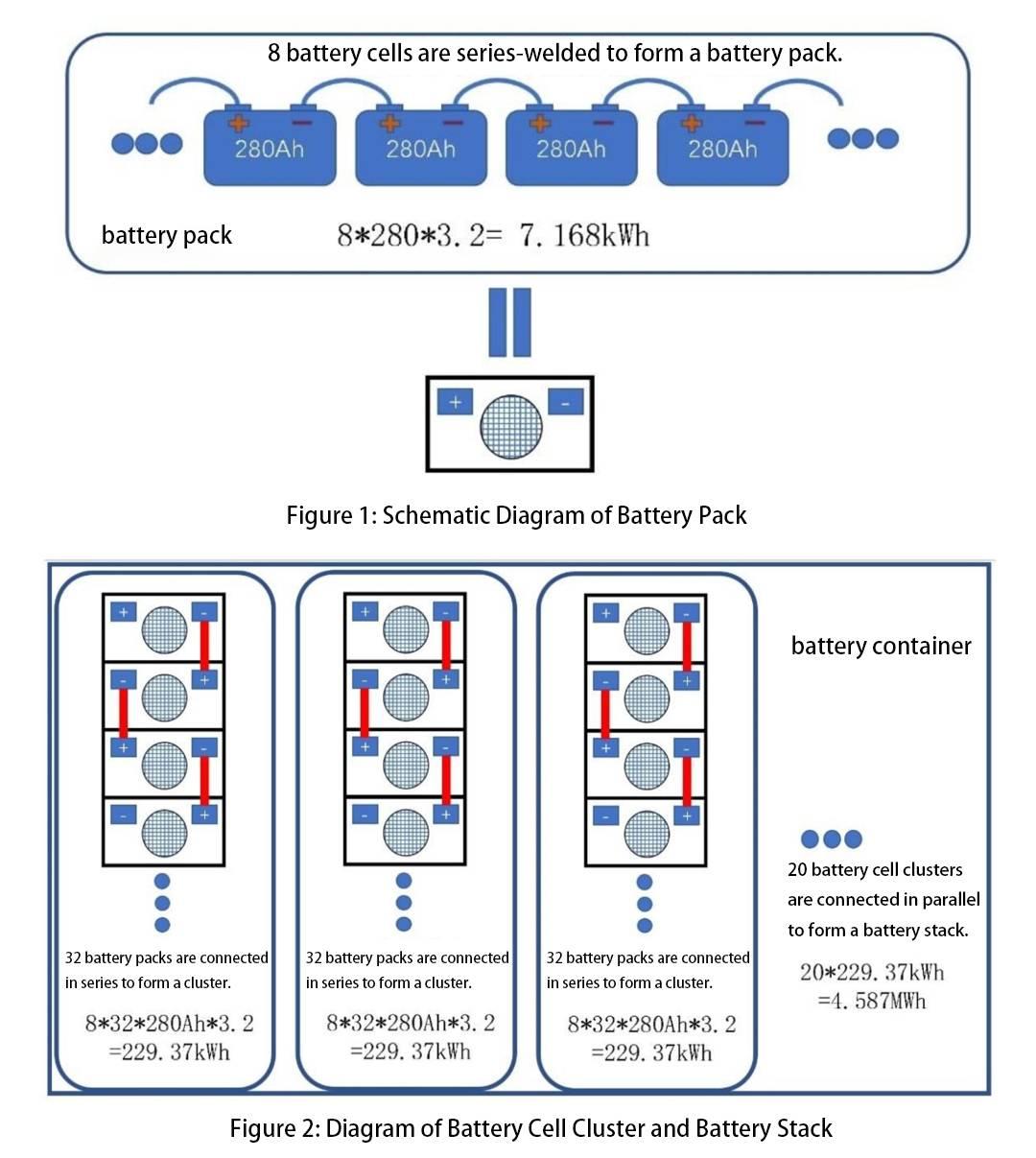
The first part is the battery pack section, where individual cells are connected in series and housed within a casing known as a battery pack (see Figure 1). Within the battery pack, the cells are interconnected via aluminum busbars. The bottom-level control unit of the Battery Management System (BMU) monitors each cell within the pack.
The second part is the battery cluster section, where multiple battery packs are connected in series to form a battery cluster. The voltage of the battery cluster must meet the requirements of the Power Conversion System (PCS). Currently, mainstream power converters operate on 1000V and 1500V DC systems. For a 1000V system, 256 cells of 280Ah each need to be connected in series to form a battery cluster, requiring 32 packs connected in series (256/8 = 32). Copper busbars are typically used for interconnecting the packs. With this configuration, the capacity of one cluster would be 256 * 280Ah * 3.2 = 229.37kWh. This layer corresponds to the second-level control unit of the Battery Cluster Management Unit (BCMU).
The third part is the battery stack management section, where multiple battery clusters are connected in parallel to form a large energy storage stack. For example, combining 20 clusters into a single container would result in a capacity of 4.587MWh (229.37kWh * 20). A 100MWh electrochemical energy storage system would require 22 such containers. The stack is controlled by the third-level control unit of the Battery Array Management Unit (BA). Figure 2 illustrates a schematic of the battery cluster and battery stack.
Based on the overall architecture of the battery system, the BMS system architecture corresponds accordingly (see Figure 3). Generally, for large-scale electrochemical energy storage systems, the BMS system is divided into three layers.
The bottom layer architecture is the BMU (Battery Management Unit). Each battery pack is equipped with a BMU system, which collects the voltage and temperature of each cell inside the pack through voltage and temperature acquisition lines. Additionally, the BMU system receives commands from the Battery Cluster Management Unit (BCMU) system and controls the operation of fans inside the battery pack.
Furthermore, the BMU device actively balances the cells inside the pack through balancing harnesses. The balancing current typically ranges from 3A to 5A.
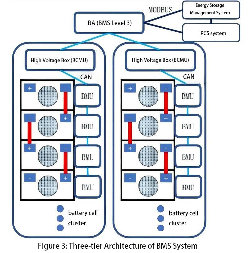
The second layer of control is the Battery Cluster Management Unit (BCMU) for each battery cluster. The BCMU receives voltage and temperature data from each cell within the cluster via CAN communication from the BMU, and also measures the current within the cluster. Additionally, the BCMU unit controls the operation of breakers and contactors inside the high-voltage box based on internal protection parameters. For water-cooled energy storage systems, the BCMU also controls the operation and power of the entire cluster's water-cooling units.
The third layer of control is the Battery Array (BA) system, which collects data from all cells within the entire battery stack. It communicates with the PCS (Power Conversion System) and the backend EMS (Energy Management System) in real-time, uploading cell data to the EMS for monitoring and transmitting relevant alarms and protection actions to the EMS system. In case of emergencies, the BA communicates with the PCS via dry contacts to initiate emergency shutdown.
A robust BMS system generates accurate outputs from inputs under expected operating conditions and environments. External factors may interfere with the BMS's correct outputs, such as environmental temperature affecting State of Charge (SOC) accuracy or contactors not responding correctly to commands. This necessitates a BMS system with strong robustness.
For the software functions of the BMS, they can be divided into device drivers at the lower level, hardware interface programs, and upper-level computational decision-making programs.
For the BMU system, its main function is to collect voltage and temperature data from each cell and upload it to the BCMU. The BMU performs basic logic control, such as monitoring for voltage and temperature out-of-range alarms, and transmitting these alarm signals. The BCMU, as the cluster management unit, utilizes complex algorithms and models to assess the operational status of the cells and further uploads the data to the BA.
The BA should function as a computer equipped with extensive data processing capabilities and configured with a database. It can perform historical data analysis and optimize cell models further. Once optimized, the latest models are sent down to the BCMU unit. Only through such layered control can the BMS meet the requirements for real-time and precise control.
Hardware Architecture
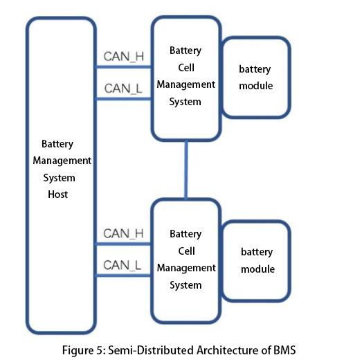
The hardware architecture of large-scale electrochemical energy storage BMS can be divided into two types: distributed architecture and semi-distributed architecture (see Figure 5). Distributed architecture has been discussed in the previous section.
Its main feature is high modularity, and in highly integrated systems in the future, the charging circuit detection may be directly integrated into the battery module. For semi-distributed architecture, the Battery Management Unit (BMU) is responsible for a battery pack and can operate with high-voltage measurement and control equipment. This module may include high-voltage measurement, contactors or relays, fuses, and current sensors or shunts. Such modules make the system easier to scale.
The power supply for the battery management system (BMS) can come from several possible sources. The BMS can be powered directly by the battery pack, or it can be entirely powered by an external control power source. Each power supply method has its advantages and disadvantages.
If powered by the battery pack, the BMS has the capability of black starting, meaning it can detect the operational status of the energy storage system even when external power supply voltage (including UPS systems) is lost, supporting black start of the energy storage system.
However, this power supply method draws power from the battery end, which over time can lead to voltage drop of the battery (i.e., increased self-discharge of the battery cells), and due to inconsistency inside the cells, the voltage drop of the battery cells is inconsistent, resulting in increased inconsistency of the whole energy storage system.
If the BMS system is powered externally, the above problems do not exist, but when the external power supply disappears, the BMS system also exits the operation. Therefore, we can set a switch device inside the BMS. In normal conditions, the BMS can be powered by an external power source. In the case of the external power supply shortage, it can be switched to battery power supply, thereby combining the advantages of both to further enhance the reliability of the system.
The battery measurement circuit should provide high DC impedance to the battery cells to minimize parasitic power consumption. Besides maintaining low power consumption, the power differences between different cells should not be too great, as this exacerbates cell imbalances and reduces battery performance.
During system standby, minimizing standby current is essential to ensure the battery management system does not deplete battery charge. Therefore, reducing the energy consumption of the measurement circuit is a common goal across all battery management system architectures.
The BMU measures the voltage of all cells within the battery pack and can also collect the total pack voltage. These redundant measurements help detect many potential faults effectively. In other words, the sum of individual cell voltages within the pack should equal the total pack voltage. These measurements are used to analyze system errors in cell voltage acquisition and make corresponding corrections to prevent risks of overcharging or overdischarging due to primary measurement errors. Averaging redundant voltage measurements can improve measurement accuracy.
Furthermore, the accuracy of voltage measurements affects the normal operating voltage range of the cells. Assuming a measurement error ΔV exists, for a measured voltage Vm, the actual battery voltage lies within the range [Vm - ΔV, Vm + ΔV].
To ensure cells operate within specified charge and discharge ranges, during charging, the BMS controls the maximum cell voltage by setting it to the upper limit voltage minus the measurement error ΔV, thereby preventing overcharging. Conversely, during discharge, the minimum voltage is set to the lower limit voltage plus the measurement error ΔV, thus preventing overdischarging.
This effectively reduces the range of cell charge and discharge voltages. Additionally, voltage measurement accuracy directly affects State of Charge (SOC) calculation accuracy. For a given voltage-dependent SOC function SOC(V), the actual SOC range is [SOC(Vm - ΔV).
Series current measurement is another fundamental battery parameter measured by the battery management system, and similar to voltage measurement, multiple redundant current sensors may be required for accuracy. When selecting current sensors, consideration must be given to ensuring they have a sufficiently wide measurement range, as measurement errors can depend on the full-scale range of the chosen current sensor.
Additionally, for applications where battery currents change rapidly, the bandwidth and frequency response of the sensors must be considered to ensure they can capture dynamic current changes effectively.
Shunt resistor: A shunt resistor is a precision resistor with very low resistance. The resistance is small enough that the voltage drop across the shunt resistor in high-power current paths within the battery system can be negligible, yet large enough to be accurately measured by the battery management system. The schematic diagram of a shunt resistor is shown in Figure 6.
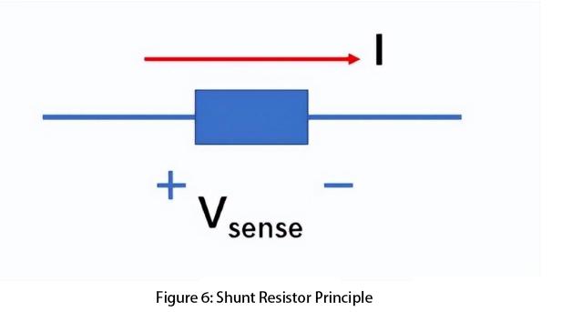
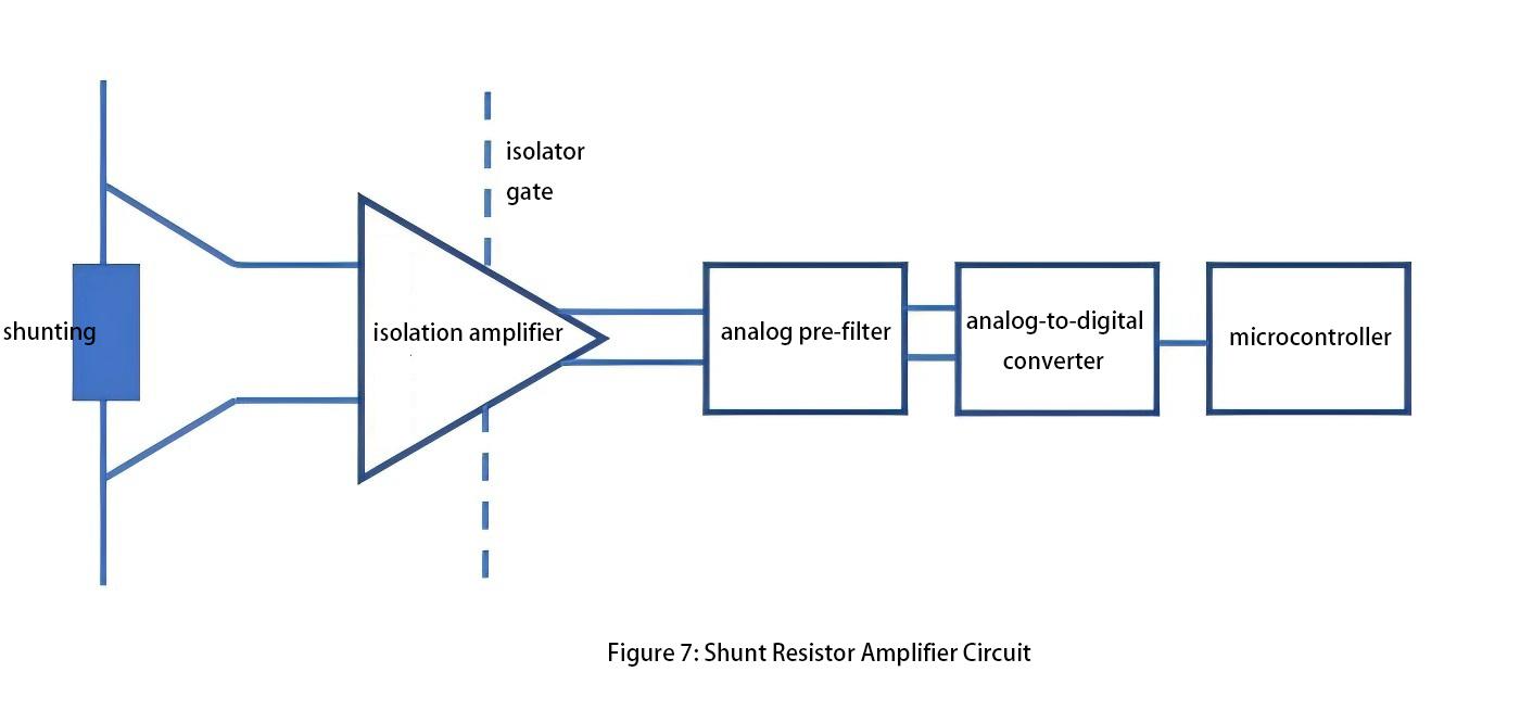
The shunt resistor is inexpensive, comes in a variety of types, and does not require an external power source. Typically, the measurement accuracy of a shunt resistor can reach 0.1% to 0.5%. Additionally, the shunt resistor amplifier circuit requires high common-mode rejection ratio, low DC offset, high gain, and good thermal stability (see Figure 7). For systems operating over a wide temperature range, the battery management system must consider the variation of shunt resistor resistance with temperature.
Hall Effect Sensor: The Hall effect is the generation of a voltage proportional to the current in the presence of a magnetic field. Unlike shunt resistors, Hall effect sensors require external power supply. There are two types of Hall effect sensors: open-loop and closed-loop. The closed-loop type includes an additional coil around the magnetic core. By controlling the current magnitude and direction in this coil, the total magnetic flux in the core can be set to zero, proportional to the desired current and battery current. Closed-loop sensors offer higher accuracy and response time, are less prone to magnetic saturation, but are larger in size and higher in cost.
Most Hall effect sensors exhibit zero offset error, which varies with temperature. Such errors significantly affect State of Charge (SOC) calculations using Coulomb counting. For instance, a current sensor with an offset error of 0.001C will accumulate a 16.8% SOC error after one week of operation. Therefore, zero-drift compensation and zero-current elimination are used in Hall effect sensors to mitigate the impact of zero offset error.
When the BMS system evaluates the operational status of battery cells, it requires synchronized data acquisition of voltage and current. The simplest method for synchronizing current and voltage acquisition is to measure all voltages and currents within a very short time frame, minimizing differences to negligible levels. Additionally, incorporating timestamps into measurement devices ensures accurate battery state estimation.
The BMS plays a critical role in thermal management based on the core temperature to ensure it operates within the specified temperature range, while also controlling the temperature difference within the same battery stack or cluster. Thermistors are one of the most common devices used in embedded systems for temperature measurement.
The resistance of a thermistor changes with temperature, classified into negative temperature coefficient (NTC), where the resistance increases as the temperature decreases, and positive temperature coefficient (PTC), where the resistance increases with temperature rise.
Under normal conditions, lithium-ion batteries operate within the range of -5°C to 35°C. It requires high accuracy in thermistor measurement within this range because cells may experience thermal runaway and other anomalies. Therefore, thermistors must have a wide measurement range, although measurement precision can be reduced outside this temperature range. In the design of temperature measurement, the following aspects should be considered:
1. What is the difference in the measured highest/lowest voltage in the battery system and the actual highest/lowest voltage of the cells? Because batteries themselves may have thermal gradients, it is necessary to measure this actual maximum difference under various experimental conditions.
2. How much lower is the measured temperature compared to the core temperature of the cells during maximum power charging and discharging scenarios? BMS temperature measurement is typically limited to the battery surface temperature, while there exists a difference between the internal cell temperature and the battery surface temperature. In extreme cases, it is necessary to determine whether the internal cell temperature exceeds the safe temperature range, requiring detailed verification under various laboratory conditions.
3. A scenario to consider is when an individual cell may experience an internal short circuit, leading to temperature rise and even entering a thermal runaway state. The BMS needs to quickly identify such faults based on temperature rise rates, temperature ranges, and other indicators, thereby promptly isolating the fault.
Please see the next article:
Overview of Large-Scale Electrochemical Energy Storage Battery Management System-BMS (二)
Next:Overview of Large-Scale Electrochemical Energy Storage Battery Management System-BMS (二)
Previous:Characteristic Advantages of CATL Tener Energy Battery Storage Container System
Contact Person: Miss. Kiki
| WhatsApp : | +8617763224709 |
|---|---|
| Skype : | +8617763224709 |
| WeChat : | +8617763224709 |
| Email : | kiki@lifepo4-battery.com |
